Embedded Programming
Table of content:
1 - Hello World - Embedded C - Arduino IDE2 - Arduino UNO - Embedded C - Arduino IDE
3 - Arduino UNO - Pure C - Arduino IDE
4 - Hello world - Pure C - Arduino IDE
5 - Hello world - Pure c - AVRdude(gitbash)
6 - ESP32 - MicroPython - ThonnyIDE
7 - datasheet attiny1614
8 - Group assignment
In this week of embedded programming, we were suppose to program our "Hello World" board with our "Programmer". Apart from the hello world
board we explored few other board and program them using different languages under different developement environment.
Here is the list of the boards, languages and environment i explored this week,
Boards
Arduino UNO
Hello World
esp32
Languages
Embedded C
Pure C
MicroPython
Environment
Arduino IDE
Avrdude (gitbash)
Thonny IDE
Here are the list of all the combinations i tried with their following results,
Hello World - Embedded C - Arduino IDE
In the week of electronics design, we had to make our own hello world board and program it with the help of programmer(which we build
in the week of electronics production) to check if the board actually functions or not. At that time i had programmed the hello world board
using arduino language with the adtuino IDE so that when i press the push button, the LED will glow. I didn't tried it again this time, so I am
just mentioning the code and the results here,
the code i used,
you can copy the code from here too.
I am explaining in brief what i understand about the embedded c code written above,
In the void setup () you define the pin modes, whether the pin should be considered as input or output. If you want
any data to show in the serial monitor, you write Serial.begin(9600); . In the void setup you usually declare things
In the void loop() you write the function which you want to perform repeatedly.
In the void setup there is written pinMode(2, OUTPUT); where we are declaring pin 2 as output pin, that is
where i have attached the LED and in the pinMode(3, INPUT); where we are declaring pin 3 as input, that is
where i have attached the push button.
In the void loop, there is written buttonState = digitalRead(3);; which means we are telling the controller to read
the state of the push button, whether it is pushed or released, more on this later. Later in the void loop there is written
if (buttonState == HIGH) {
where we are telling the controller that if the button state is high, mwaning if the button is being pushed, digitalWrite(2, HIGH); meaning
make the pin 2 high meaning pass the current to the pin 2 making the led glow. Else, digitalWrite(2, LOW); meaning turn the led off.
here are the results,
// turn LED on:
digitalWrite(2, HIGH);
} else {
// turn LED off:
digitalWrite(2, LOW);
Arduino UNO - Embedded C - Arduino IDE
i tried to program Arduino UNO using Arduino language with Arduino IDE to give blinking effect to two LED's,
Here is the code I used,
you can copy the code from here too.
Here are the results,
Arduino UNO - Pure C - Arduino IDE
This time i tried to program Arduino UNO using Embedded C language with Arduino IDE to give blinking effect to two LED's,
Arduino is comparatively simple and wasy to understand languange than Embedded C. You'll get a better idea if you compare the code written in
Arduino and code written in Embedded C so here is the code i wrote with Pure c,
you can copy the code from here too.
Here are the differences between the Arduino and Embedded C,
[1] In the embedded c, you need to include the input/output pins and delay library. While in Arduino you don't need to include any such
library.
[2] In the Arduino you define the input/outpin pin by writing pinMode(2, OUTPUT); where the "2" defines the
digital pin number written onto the UNO and "OUTPUT" defines outuput. While in the Embedded c,
you either write DDRC = 0x01; or
DDRB = 0B001000; Where DDR stands for data direction resistor and DDR decides whether the pins are imput pins or
output pins after giving the address of the pin. The letter following the DDR is the name of the port, DDRA means pins in port A, DDRB means
port B and so on. Every integrated circuit(IC) has their designated port pins named by PA, PB, PC and you can see that in their pin out.
This is the pinout of the UNO,
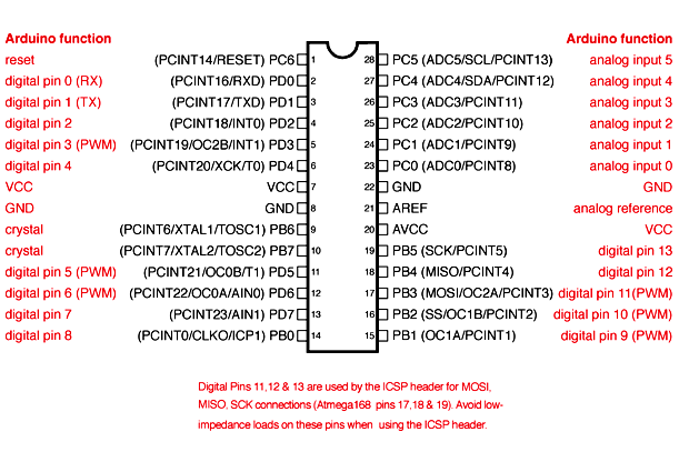
As you can see in the image above, the digital pin 9, 10, 11, 12, 13 in Arduino UNO means PB1, PB2, PB3, PB4, PB5. This clearly means that in
embedded c you cannot use the digital pins that are assigned to the board but you need to take the reference of the port pins.
After selecting the port by writing DDRA/DDRB you need to give the address of the particular pin. The address is either written in binary form,
0bx00000100; where the 0b represents binary or the address is written in hexadecimal form,
0x01; where the 0x represents hexadecimal.
this is how i calculated the address of the pin for UNO,
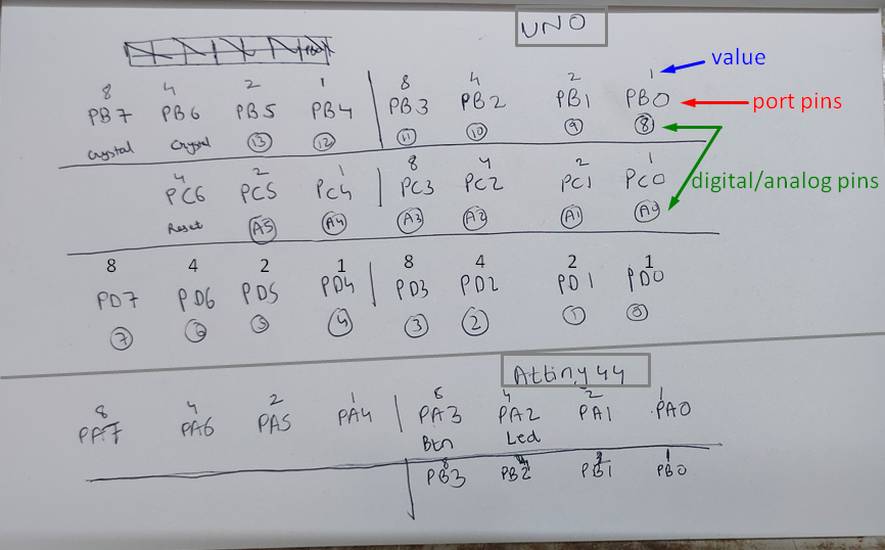
reference link: https://components101.com/microcontrollers/arduino-uno
calculating the address in binary form: after refering to the pin out of the UNO, write all the port pins(PB1/PC1) in the middle.
Write the associated digital/analog pins(1/A1) number below the port pins. Starting from PB0/PC0 make a partition after four port pins and
assign them value 1 for PB0/PA0, 2 for PB1/PC1, 4 for PB2/PC2, 8 for PB3/PC3 and write that value below port pins.
now lets say you have attached a LED onto digital pin 6(PD6) so the PD6 pin will be output hence PD6 will be 1 and rest of port D pins
will be 0. So,
PD7 = 0
PD6 = 1
PD5 = 0
PD4 = 0
PD3 = 0
PD2 = 0
PD1 = 0
PD0 = 0
so the address for defining digital pin 6 as output in binary form will be 0b01000000;
calculating the address in hexadecimal form: in hexadecimal instead of writing 1, you need to write the value of the port pin which
you want to assign as output pin amd for the rest, write 0 as the value. Now lets say you have 6 leds attached from digital pin 0 to 5(PD0 to
PD5). The value for the pins will be
PD7 = 0
PD6 = 0
PD5 = 2
PD4 = 1
PD3 = 8
PD2 = 4
PD1 = 2
PD0 = 1
the total of PD7 to PD4 is 3 and the total of PD3 to PD 0 is 15. so the address for defining digital pin 6 as output in binary form will
be 0x3F;
In hexadecimal you can write digits only upto 9. After 9 you need to assign the letter like 10 = A, 11 = B......15 = F and so on.
[3] In the arduino, you write digitalWrite(2, HIGH); if you want to turn on the LED on pin 2 and you write
digitalWrite(2, LOW); if you want to turn off the led on pin 2. In embedded c if you want to turn on the led you
you write PORTC |= 0x01; where |= is HIGH and to turn off the led you write
PORTC &= ~ 0x01; where &= ~ is LOW. The delay in Arduino is defined as
delay(1000); and in embedded c you write delay as _delay_ms(10);
Here are the results,
Hello world - Pure C - Arduino IDE
As tou have seen above, in the electronics design week i had programmed my hello world board with Arduino language where the LED will glow when
i push the push button. This time i wanted to try the same, but with embedded c language.
Here is the code I used,
you can copy the code from here too.
Here are the results,
for some reasons the outcome of the push button with led was very weird. Initially it was working fine like the led will turn on only when the
button is pushed and it will turn off when it is released. Then the led seemed to be froze, like there was no effect of the push button on the
led. And then turning off of the led was random, like sometimes the led will turn off when the button is released and sometimes the led will
froze with no effects of push button on it.
I thought there might be some issue with the connections in the board so i tweaked the code a little bit to give blinking effect when the button
is pushed. Here is the code with the blinking effect,
you can copy the code from here too.
and here is the results,
as you can see, the push button and the led works fine after adding the blinking effect. I then again tried to upload the button code with
arduino language(the fist code in this tab) and as expected, it was oworking fine(i don't know why i didn't tried it first before trying
with the blinking effect). So i knew there was something wrong with the code. I then showed all three codes with their results to one of my
local instructor and after few trials she was successful with getting a code which works exactly like the button code in the arduino language.
Here the code she edited in the buttonled.ino,
you can copy the code from here too.
Hello world - Pure c - AVRdude(gitbash)
Since i had yet to explore the AVRdude environment, i deccided to try the code which my instructor edited, in the AVRdude environment. Here is
how i programmed my hello world board using embedded c language with AVRdude environment,
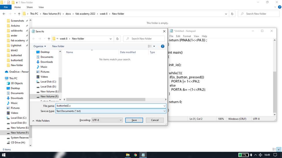
[1] copy the code and paste it into the notepad. Save the notepad file as source file with ".c" at the end of the file name. You can
keep the file type as Text Documents or All files, it doesn't matter.
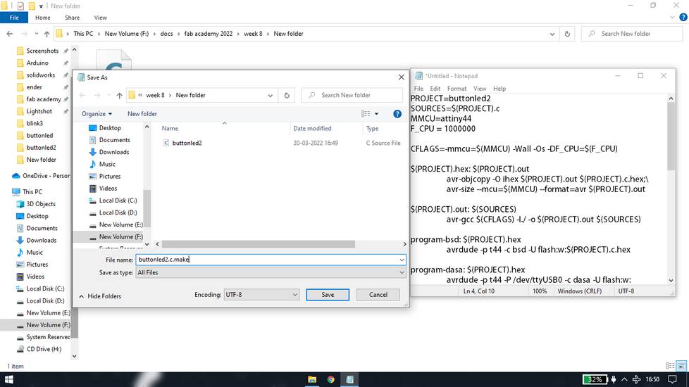
[2] you can get the make file from here: http://academy.cba.mit.edu/classes/embedded_programming/hello.ftdi.44.echo.c.make
copy that and paste it into the notepad. You need to edit the name of the source file mentioned inside, you can also change the name of the
IC and frequency. My colleagues had already done the trial and error, so i directly set the frequency to 1MZ. After making the necessary
changes save the notepad file as make file with the same name as the source file, but just add ".make" at the
end of file name. For example you have given the source file name as xyz.c then name the make file as xyz.c.make. select the file type as all
files.
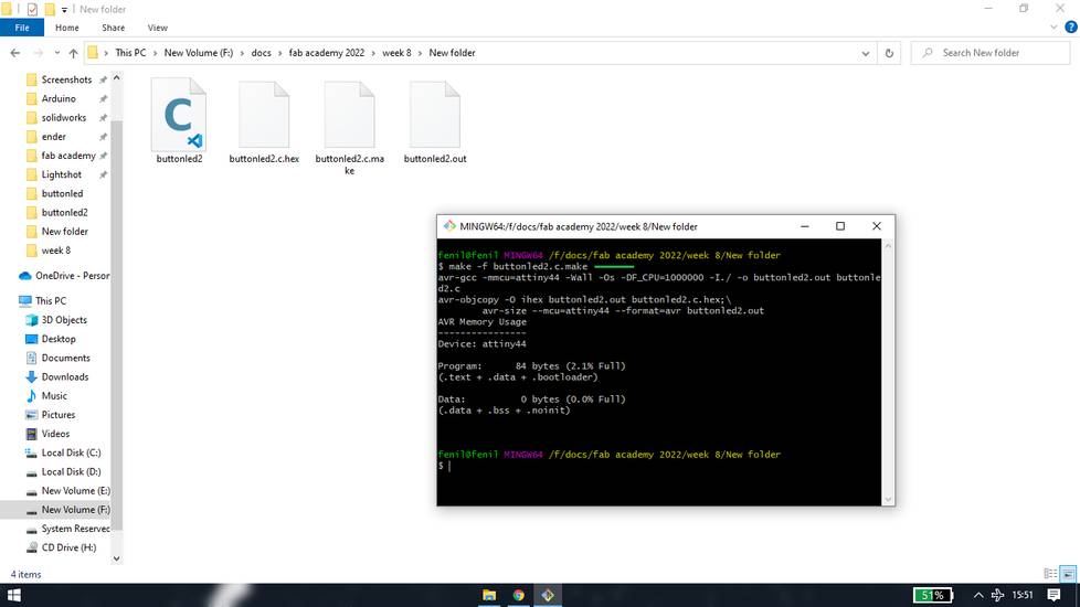
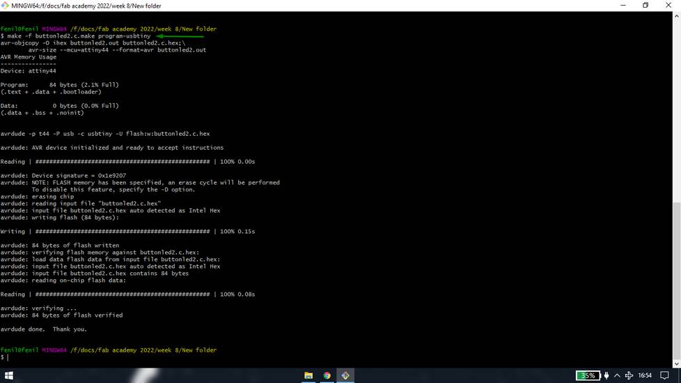
With the source file and make file into one folder, execute this three commands into gitbash,
make -f buttonled2.c.make
open git bash and set the directory where you have saved the source file and make file or you can go to that folder and right click > select
git bash here. You need to write name of you make file in the place of "buttonled2.c.make"
after executing the make command, you will see that two files will be added into the folder, make file and out file.
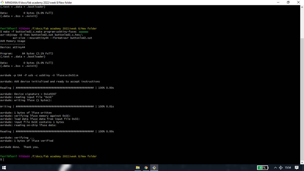
make -f buttonled2.c.make program-usbtiny-fuses
Again you need to write name of you make file in the place of "buttonled2.c.make"
make -f buttonled2.c.make program-usbtiny
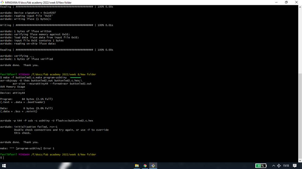
I was getting some kind of error while executing this command. I thought there was some kind of typing mistake so I again re-write the command
and this time the code was executed without any error,
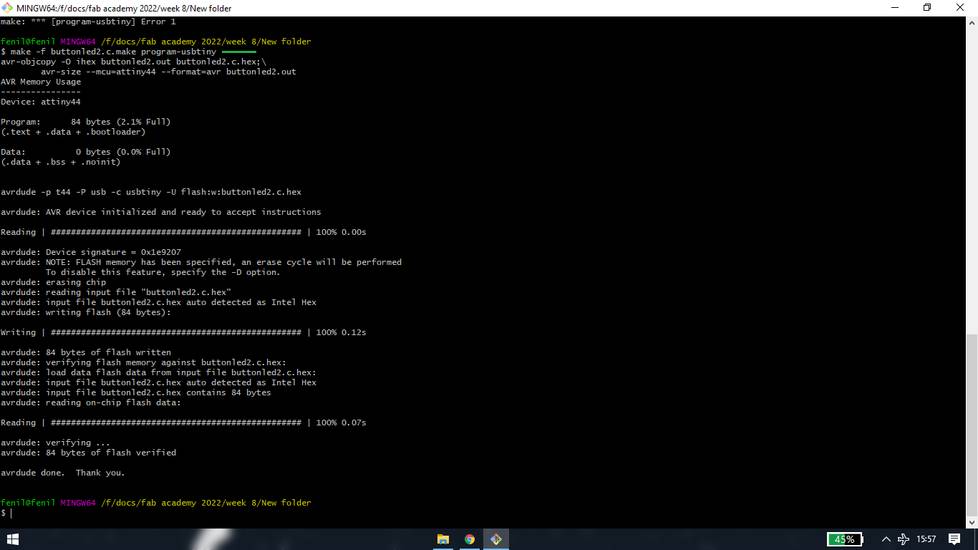
the program was executed successfully but the push button and led was not functioning at all. So I tried to upload some other program using
arduino IDE and arduino language, and i was getting error while uploading the sketch,
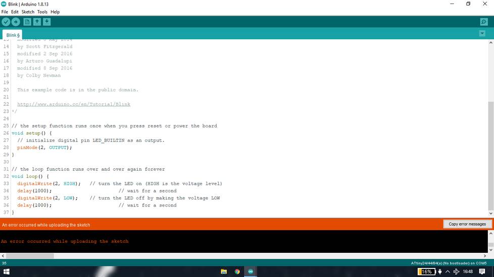
i tried few things like changing the USB extension cable, changing the port i was using, changing the ribbon cable, but i was still having the
error while uploading the sketch. Then I burrowed my
colleague's hello world board and i was facing no error while uploading the sketch into his hello world board. I then checked few conections
using continuity function of the multimeter to see if there any problem with the connection since there is comparatively more stress on the
header pins than other components and i found there was no problem with any connections.
One of my colleague had faced the same issue of getting the error while uploading the sketch. When i asked him how did he solve the problem,
he told me that he changed his hello world board IC. Then my other colleague took my hello world board and did some reflow onto the IC pins,
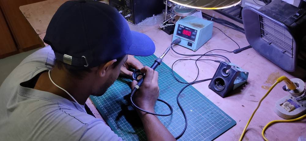
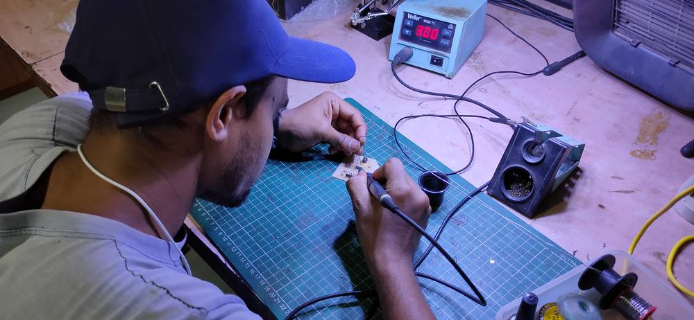
after the reflow/resoldering, my hello world was back to normal and i was facing no issue while uploading the sketch.
and here is the result,
ESP32 - MicroPython - ThonnyIDE
Lastly i tried esp32 board using micropython language with thonnyIDE. I was following this tutorial:
https://randomnerdtutorials.com/getting-started-thonny-micropython-python-ide-esp32-esp8266/
You can go through the blog, the steps mentioned there are well explained and fairly detailed. I will mention few of the steps here in brief,
[1] Install ThonnyIDE
you can download the thonnyIDE from here: https://thonny.org/
[2] Flashing the MicroPython firmware into ESP32
By default, esp32 cannot understand micropython language so we need to flash the micropython firmware into the esp32 using thonnyide. You can
download the micropython firmware for esp32 from here: https://micropython.org/download/esp32/
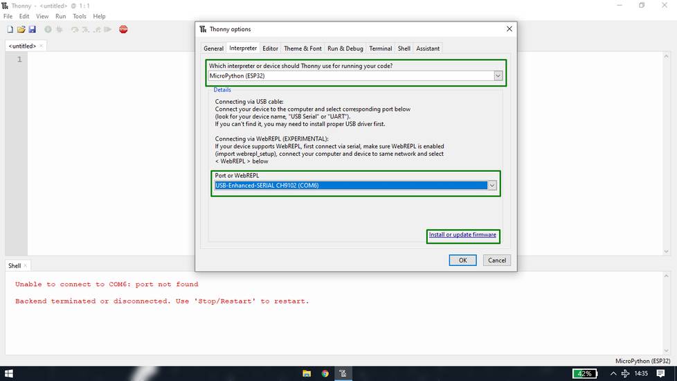
After downloading the firmware, connect tghe esp32 into your system and open thonnyide and go to Tools > Options > Interpreter. Under the
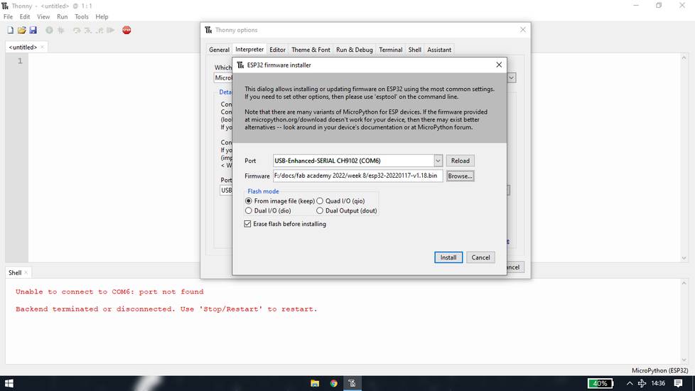
interpreter, select "MicroPythonESP32" and under port select the port. Then click on "Install or update firmware".
A new window will pop
where you again need to select the port and give the file path where you have downladed the firmware. Click on install and your firmware
will be installed. (((ss of the installations)))
[3] Checking if the firmware is installed properly
Go to Tools > Options > Interpreter and select the correct interpreter and port. Under the shell section type help() .
If it responds back with "Welcome to MicroPython on the ESP32" that means the firmware was installed sucessfully.
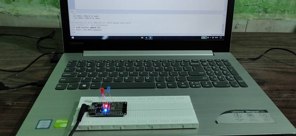
In the shell section write these command one by one,
from machine import Pin
Pin(2, Pin.OUT).value(1)
and you'll see that the in-built led in your esp32 will turn on.
I then tried to program the esp32 by writing the code in the editor section. First save the file in your system and name it as "main.py"
if you give any other name, the program will not work!
this is the code i used for turning on the led,
    from machine import Pin

    from time import sleep

    led = Pin(27, Pin.OUT)

    while True:

      led.value(not led.value())

      sleep(0.5)
After writimng the code, go to File and select Save as and this time select "MicroPython decice" and your code will be uploaded. Unlike arduino
UNO, it won't directly show the effect. You need to press the "en" or "reset" button on the esp32 and then the code will come into effect.
here is the result,
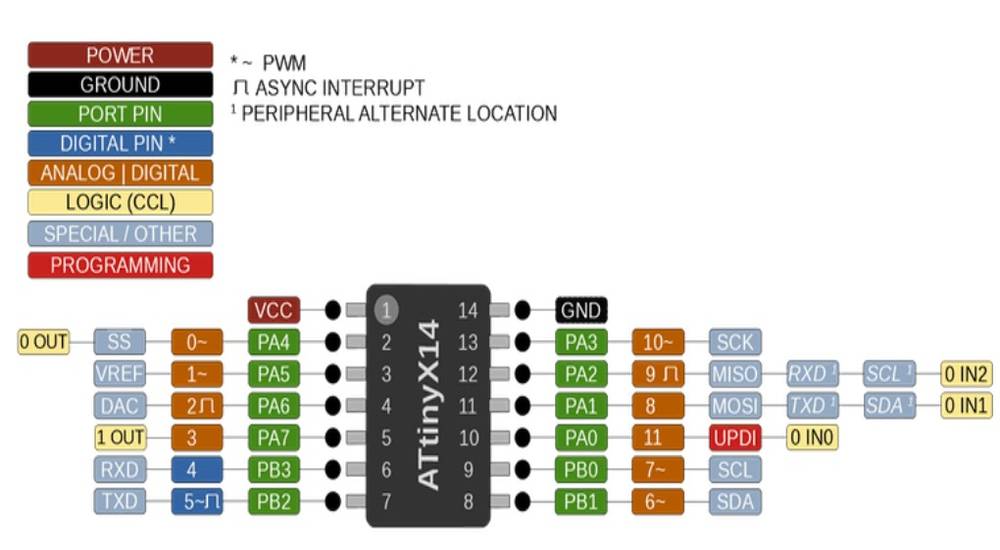
in the individual assignment, we had to read the datasheet of microcontroller. For my final project, i initially decided to use attiny1614
IC.
You can download the datasheet for attiny1614 from here:
https://ww1.microchip.com/downloads/en/DeviceDoc/ATtiny1614-16-17-DataSheet-DS40002204A.pdf
Here is all the things i got to know after going through the data sheet,
- attiny1614 has 14 pins. 10/14 pins can be used as analog pins: PA0-PA7 and PB0-PB1. 2/14 pins can only be used as digital pins: PB2-PB3.
6/14 pins can be used as PWM pins: PA3-PA4-PA5 and PB0-PB1-PB2.
- attiny1614 has 2KB of SRAM
- attiny1614 has 16KB of FLASH memory.
- attiny1614 has 256 bytes of EEPROM.
Here are the provision of the pins,
- if you want to use I2C devices like OLED, you need to connect the SDA-SCL pins on PB1-PB0 pins of the IC.
- if you want to read the data serially into the seria monitor, you need togive the provision for TX-RX on pin PB3-PB2.
- for programing the attiny1614 you'll need a programmer and you can program it with PA0 pin which is the UPDI pin. If your programmer have
TX-RX pin instead of UPDI pins, you can use a serial to UPDI converter.
Group assignment
For the group assignment we explored different architecture like Arduino UNO, Hello world and esp32 with different languages like Embedded c,
Pure C and MicroPython with different environment like Arduino IDE, AVRdude(gitbash) and Thonny IDE, detailed description of which
you'll find above. For more details regarding group assignment you can visit here:
https://fabacademy.org/2022/labs/vigyanashram/groupassig/groupassignment6.html
Drip Irritation by Fenil Chandarana is licensed under Attribution-NonCommercial-NoDerivatives 4.0 International![]()
![]()
![]()
![]()